3 min to read
The Meaning of Y-cap in Battery Electric Vehicles
Why Y-Cap is an important design factor?

Y-capacitors and X-capacitors are commonly used in high-voltage or traction voltage systems (TVS) in battery electric vehicles (BEVs). These capacitors are also present in charging equipment. To understand their importance, we need to know about different types of electrical noise. This article explains normal mode and common mode noises in high-voltage systems.
For those new to BEVs, a quick overview of the high/traction voltage system (TVS), low voltage system (LVS), and signal system (SS) is provided at the end. The different types of safety capacitors (X-cap and Y-cap) and their uses are detailed in this article. Another article discusses how Y-caps are used in energy storage systems (ESS).
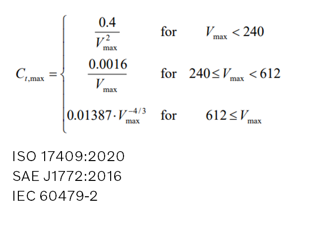
In BEVs, Y-caps are more relevant since TVS primarily consists of DC bus lines. Most high-voltage components, including the ESS and auxiliaries, have one or more Y-caps. When charging through an EVSE (electric vehicle supply equipment), these capacitors consume a small amount of energy before the ESS starts charging. Regulations limit the total energy stored in Y-caps to no more than 0.1 joules at any time. Therefore, the total Y-cap value must be within a certain range to meet these regulations.
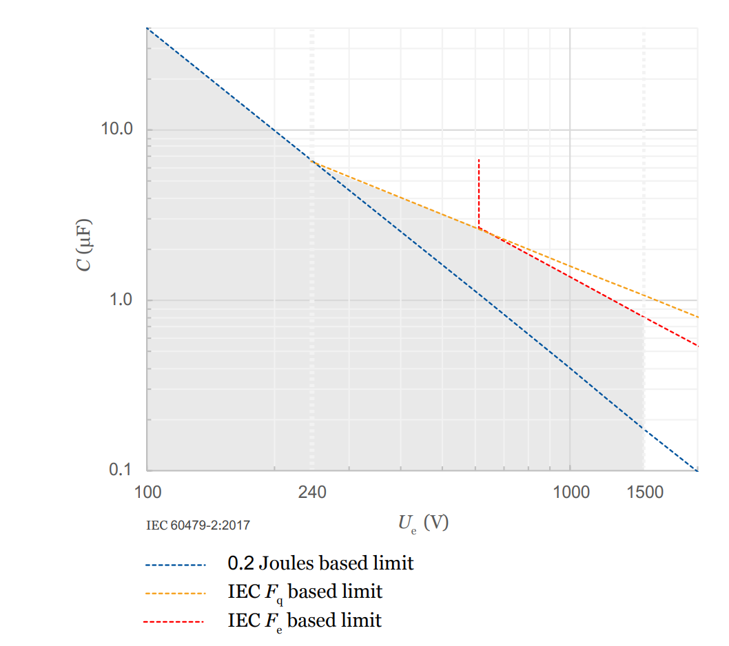
If the Y-cap value exceeds the limit, the EVSE may detect an anomaly and stop charging. This is why having too many high-voltage components in a BEV can cause charging issues. The graph below shows the regulated Y-cap value for BEVs.
 |
|---|
| Capacitance limit vs. Voltage. The blue line shows the 0.2 Joules limit set by several standards (Source: Sendyne) |
The Y-cap value depends on the number of high-voltage components and the traction voltage level. Suppliers typically provide the Y-cap values for individual components. Based on the connections (series or parallel), the overall Y-cap value for the system can be calculated.
 |
|---|
| Capacitance limits depend on voltage. Relevant regulations for Y-caps in EVs |
In a typical TVS, high-voltage components are connected in parallel, increasing the overall Y-cap value.
 |
|---|
| Capacitors in parallel increase the overall capacitance |
To address charging issues caused by high Y-cap values, Sendyne is developing ways to dynamically measure Y-cap values. This could help EVSEs make better decisions before interrupting charging sessions. However, meeting the regulation to limit total stored energy remains a challenge.
Traction Voltage System
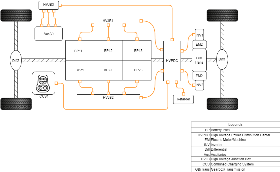
The TVS in most BEVs is a floating system, with all high-voltage components grounded individually to the chassis, as shown below. Designing a safe and efficient TVS involves many considerations, including:
- Cable size
- Cable length and routing
- Connector choice and HVIL compatibility
- Ground cable size and length
- Total Y-cap value for the vehicle (as discussed above)
Separate blogs will explore these topics in detail.
 |
|---|
| A typical traction voltage topology |
Low Voltage System
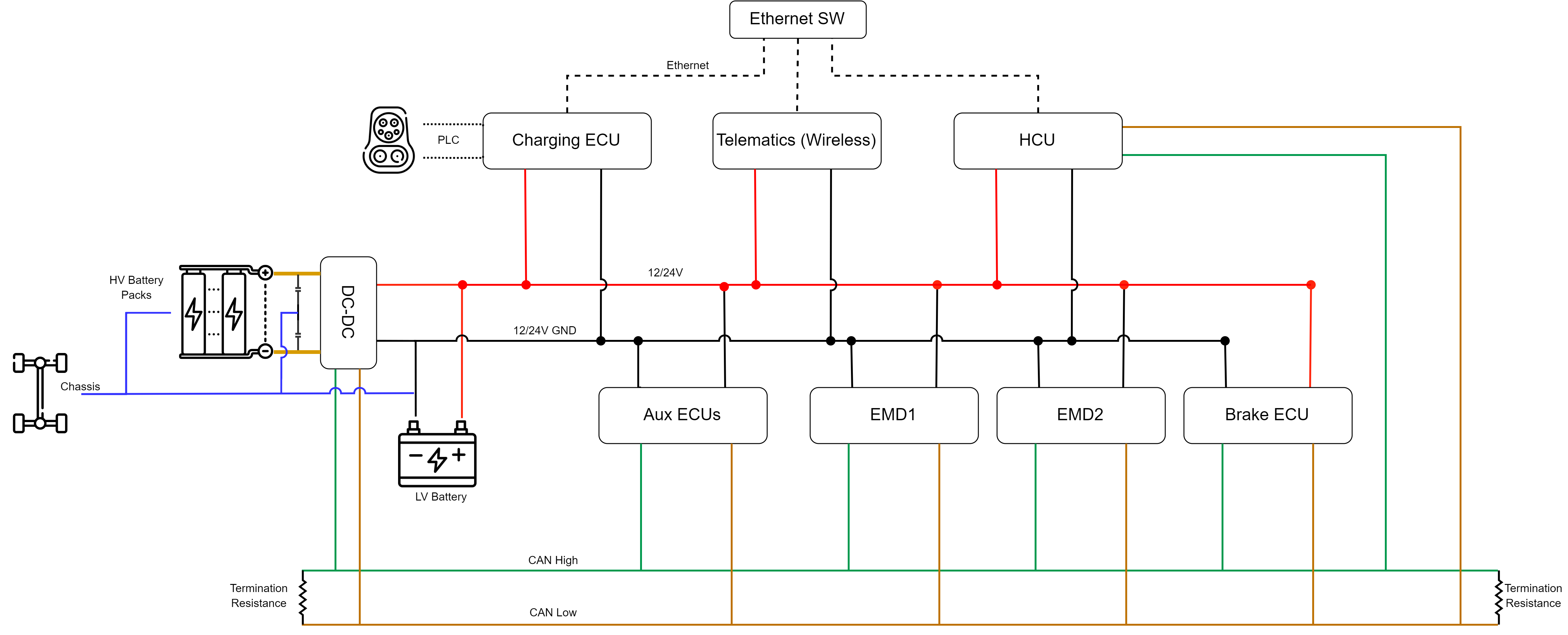
The LVS is common to both ICE vehicles and EVs. While 12V systems are standard, 24V and 48V systems are becoming more common. Hybrid systems, where both 12V and 24V/48V coexist, are also possible. CAN, Ethernet, and LIN nodes are typically part of the LVS. Below is an example of an LVS, which includes a high-performance ECU for tasks like image processing and adaptive AUTOSAR architecture. A future blog will discuss adaptive AUTOSAR in detail.
 |
|---|
| An example of a low voltage topology |
Physical Layout
The physical layout of high- and low-voltage harnesses is crucial for managing packaging constraints and meeting communication standards. For example, $J1939-11$ specifies a shielded twisted pair of wires with a maximum backbone length of $40$ meters, supporting up to 30 nodes with a 4.00 μs bit time and 0.05% tolerance. Relevant links are provided below:
Overall EV Regulations
FMVSS Standards
J1939 Physical Layer
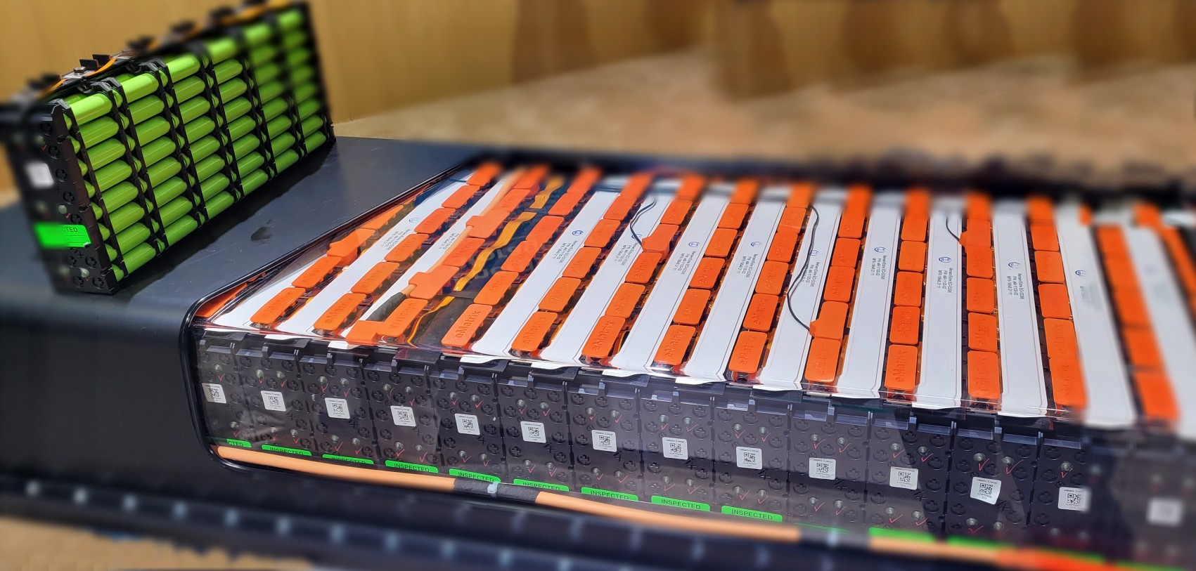 |
|---|
| An electric battery pack on display at ACTExpo 2022 |
Comments